Treatment process
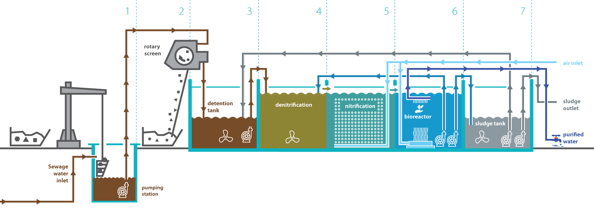
Input pumping station – 1
The input pumping station is used to pump wastewater from the inflow sewerage level to the accumulation section of the process tank. The pumping station (PS) consists of a shaft with a diameter of 2-2,5m. Its depth depends on the depth of the input sewerage, inflow unevenness and is fully adapted to the local conditions. The PS includes a bar screen basket for retaining solids with gaps between individual bar screens of 20 – 25mm. When the basket is full, it is emptied into a collecting container using a bracket jib crane. Pumps in the pumping station will be designed for a maximum calculation inflow. One pump constitutes a 100% backup for the other one.
Mechanical pre-treatment – 2
The mechanical pre-treatment is provided by the bar screen basket in the input PS and subsequently by a rotary screen with openings with a diameter of 0.5mm. Here, insoluble substances of sizes larger than 0.5mm are separated from the inflow wastewater. Rotation of the drum pushes impurities into a chute and into an adjacent container. The rotary screen is located above the accumulation section of the process tank.
Accumulation section – 3
The accumulation tank is used to balance the inflow unevenness during the day, thus ensuring a continuous and uniform treatment process in the following sections. This section contains submersible pumps, which pump water into the next denitrification section. The pump is switched on and off depending on the setting of the level sensor and the level drop in further sections. The tank also contains a submersible propeller stirrer ensuring homogenisation of water intended for treatment. The accumulation section also receives back water returning from the sludge dewatering section.
Denitrification section – 4
The denitrification section follows the accumulation tank and is used to remove nitrogen pollution from the wastewater, namely by converting nitrate and nitrite forms of nitrogen into gaseous nitrogen. At the same time, partial degradation of carbon pollution stemming from the organic substrate takes place here. Correct functioning of the denitrification reactor requires continuous homogenisation of its content by the installed submersible propeller stirrer. The inlet of the recirculation, which ensures the return of activated sludge from the membrane bioreactor, also discharges into this section.
Nitrification section – 5
It follows the denitrification section, into which a mixture of polluted water and activated sludge flows gravitationally over an overflow edge. The nitrification section enables biological removal of carbon pollution, which reduces COD and BOD5, and, at the same time, oxidation of nitrogen pollution in the form of ammoniacal nitrogen up to nitrates takes place here. This process requires oxidation of treated water. For this purpose, fine-bubble membranes ensuring uniform airflow across the whole area of the section are located on the tank bottom. Necessary amount and pressure of air are ensured by a set of blowers located in the blowing plant.
Sludge management – 7
The last section in the process tank is the sludge tank, which is divided into two parts with a different volume by a dividing barrier. Superfluous sludge from the MBR section is pumped into the first part, whose volume takes up ¾ of the sludge collector, and not only gravitational densification of the sludge and the offsetting of sludge water, but also the completion of sludge stabilisation takes place here as it is provided with both a stirrer and aeration. The offset sludge water falls into the other tank part over the barrier and when it is full, it is pumped with the submersible pump into the accumulation tank. Homogenised sludge with dry matter of approx. 20-30g/l, which is monitored with a sludge probe, can be pumped out using a faecal suction truck or pumped into a sludge dewatering line.
Membrane bioreactor - MBR – 6
Treated water flows into the section by overflowing from the nitrification section. The section contains a membrane bioreactor embedded with membrane units with a total surface area of 420m2. Cleaned water rid of activated sludge and bacteria is extracted through pores in the membrane walls with a size of 0.04μm from the inside of hollow fibres into a collecting tank for cleaned water. The flow of the mixture of treated water with sludge around the outer walls of the membranes is solved by an aeration system located at the bottom of the bioreactor. Extraction of cleaned water from the bioreactor tank causes sludge densification in the section. Submersible pumps with a backup are located in the section together with the bioreactor. These provide the following functions: the pumps provide the pumping of the returned sludge back to the treatment process in the denitrification section. The recirculation coefficient is adjustable within the range of 2–5 times the WWTP output. An airlift pump is switched on automatically after the sludge density in the bioreactor section reaches 12-15g/l and pumps superfluous sludge into the sludge tank (sludge collector).